Crystal Bridges Museum of American Art
Contents |
[edit] Overview
Nestled into its surrounding natural landscape, the Crystal Bridges Museum of American Art, in Bentonville, Arkansas, is a sublime combination of a simple materials palette supported by complex engineering. The project is also a testament to the iconic architecture that can be achieved when engineers play an active role in design teams.
Crystal Bridges is a 18,700 sq m complex of eight interrelated structures that are thoroughly integrated into the landscape. The structures overlook two man-made ponds that act as reflecting pools and are fed by a small stream. Five of the buildings serve as art galleries, one is a café, one houses administrative offices and storage space, and the eighth structure, referred to as the Great Hall, is used for receptions.
Although each of the buildings has its own individual program and distinct form, the structures all share a clean, contemporary, and simple materials palette of concrete, wood, copper, and glass.
Based on their location, the buildings can be classified as either “land” structures or suspended “bridge” structures. The five land structures are anchored into the rolling landscape and surround the two ponds. Two of the three bridge structures act as weirs, damming the stream that bisects the site and thereby creating the two ponds. The stream is fed by the nearby Crystal Spring, the source of the museum’s name. The third bridge structure, the Great Hall, projects into the southern pond like a peninsula.
The architect, Moshe Safdie, was inspired by the suspended bridges he had seen while travelling in Bhutan.
The Crystal Bridges buildings rest on fractured limestone, a highly permeable rock with uncertain bearing capacity. Each of the buildings was designed as an independent structure with movement and expansion joints. Moreover, the bridge buildings’ abutments were physically separated from the surrounding structures to accommodate any differential settlements or induced rotations caused by the heavy cable loads that support the roofs of the bridges.
The engineers also considered the museum’s proximity to the New Madrid Seismic Zone in their provisions for seismic loading and had to accommodate the fact that the buildings were founded on soil as well as heavily fractured rock. Excavation to sound depths of rock would have required a tremendous amount of additional work, so an economical system of grade beams founded on both vertical and inclined minipiles was used.
Unlike the land buildings, which are carved into the hillside, the bridge buildings are stand-alone, detached structures. Their bases form concrete weir structures that serve as the floors of the buildings and, in the case of the two spanning buildings, also control the stream flow.
[edit] Superstructures
The geometry of the buildings, one of the most significant features of the project, encompasses not only the geometrical variation in plan but also the geometry of the roofs of the bridge buildings.
The lower levels of the land buildings are concrete frames that feature either beams or flat slabs of irregular geometry that span distances of 6 to 9m and are supported on columns that are either 610mm square or 610mm diameter. The upper-level columns and retaining walls are spanned by curved laminated timber beams 265mm by 785mm in cross section . The building roofs are made of locally sourced glulam beams and include alternating transverse strips of copper cladding and glazed skylights.
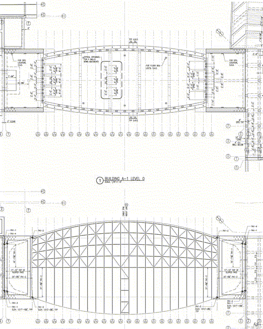
The roof geometry of the bridge buildings is configured as a series of non-repeating arches at 1.8m centres. As a result, each glulam arch has a unique inner and outer radius. The arches are each broken into three segments and taper at the ends, 265 mm wide with depth varying from 610 mm to 775 mm. These arches rest on pairs of 100 mm diameter stainless steel cables strung between heavy concrete abutments that support the roofs. The roofs and floors are connected by external steel facade mullions that both support the facades and impart additional stability to the roofs under live loads.
The glulams are connected to each other by a series of T-shaped steel purlins 125mm by 380mm in cross section located atop the glulam beams. Since the number of purlins is constant throughout the cross section, as the bridge roofs become wider, the spacing between the purlins gradually changes. This provides the T- shaped purlins with both a vertical and a horizontal inclination with respect to the glulams. Smaller, secondary timber purlins divide the roof into opaque and skylighted areas. These secondary purlins are 75mm by 150mm in cross section and have 20mm cross bracing that provides the roof plane with a structural diaphragm.
The building roof geometeries are based on catenary shapes created by the deflection of the cables. The structures were designed so that the cables carry all of the dead load. Once the dead loads of the roofs were installed, the cables deflected and attained their final geometries. The facade mullions were then added, connecting the glulam beams directly to the ground. This created stiffer load paths that carried any additional live loads from the roofs. The mullions supplement the horizontal diaphragm of the roofs and provide lateral stability under wind and seismic loading.
The bridges are suspended from abutments at either end. These abutments feature 0.9m thick walls and rest on 1.2m deep mat foundations that utilize shear keys and are located directly on rock. To resolve the overturning load created by the bridge roofs, the engineers installed rock anchors along the rear portions of the abutments; these anchors were sleeved through the abutments.
[edit] Detailing
Detailing is key to the successful construction of the complex forms used in these buildings. The geometry of the roof changes during construction as the loads build up on the suspension cables.
One of the typical and repeatable details created by the team was a visible connection between the cables and the glulams at the typical ball joint castings. The team needed to create a single, repeatable detail in all of these locations that could accommodate the number of variations for each glulam arch location along the cable.
There was a variation in the angle between the cable and the axis of the glulam in all three axes: a horizontal variation because the cable bowed out horizontally along its length; a vertical variation perpendicular to the cable because the arch radius of the glulam was different at each location; a vertical variation parallel to the cable because the cable dipped down along its length; and, finally, a variation that had to be anticipated in all of these axes as the bridge was loaded and the cable moved to accommodate the dead load.
To accommodate these variations, a 200mm diameter casting ball was attached to the 100mm diameter steel suspension cables. This detail effectively functioned as a universal joint within the degree of movement defined by the geometry of the Great Hall, which presented the most challenging conditions of all of the bridge buildings. The detail also allowed the glulam arches to remain vertical even as the roof was loaded and the cables dipped down, a condition that was essential for the erection process as well as for the final geometry.
Another custom detail was designed for the intersection between the roofs’ T-shaped steel purlins and the glulam beams, the point where the angle of the intersection varies in all three directions. At these intersections, there is variation in the horizontal plane because the purlins separate as the width of the roof increases; variation in the vertical plane because the arches rise along the body of the roof; and, finally, variation in the third plane because the roof surface is warped and therefore the steel purlins twist along their axes as they advance between the glulam arches.
This detail used a rotating plate on the shear tab located on top of the glulam. A pin connection compensates for the vertical plane and permits a twisting of the structural section. T-shaped sections were selected for these purlins on the basis of the torsional flexibility they provide.
Building Information Modelling (BIM) systems and digital fabrication techniques were used to communicate the complex geometry for construction, including the erection phases. This speeded up the construction process, simplified the production of shop drawings and ensured everyone used the same data in a coordinated way. It also helped to remove much of the risk and made it easier to ensure the correct sequence of assembly required for construction.
The BIM models helped to verify the geometric integrity of the designs in terms of the structural configurations and the complex forms. The models of the bridge buildings included the cables as well as the glulam arches and the roof construction, which yielded very precise estimates of the roof weights. These estimates were extremely important for determining the roofs’ final forms, since the geometry of the buildings was directly influenced by the loads.
[edit] Summary
The Crystal Bridges project is an outstanding demonstration of the power of engineering in unlocking a vision and creating beautiful buildings. The team used creativity, ingenuity and innovation not just in structural analysis, but also in rationalising a highly complex form to deliver a practical buildable project.
The use of a common digital fabrication model and development of standardised details for a highly variable geometry challenged the very latest modelling technology. However, it delivered a workable construction methodology that ensured value to the client and contractor through reduced risk and increased certainty.
The structure of this project is fundamental to the visitor’s experience - the strength and stability of the concrete structures anchored in the earth leading to the tranquillity of the suspended roofs floating above the works of art. It is a demonstration of the elegance and simplicity of excellent engineering.
This article was created by --Buro Happold
Featured articles and news
Gregor Harvie argues that AI is state-sanctioned theft of IP.
Preserving, waterproofing and decorating buildings.
Many resources for visitors aswell as new features for members.
Using technology to empower communities
The Community data platform; capturing the DNA of a place and fostering participation, for better design.
Heat pump and wind turbine sound calculations for PDRs
MCS publish updated sound calculation standards for permitted development installations.
Homes England creates largest housing-led site in the North
Successful, 34 hectare land acquisition with the residential allocation now completed.
Scottish apprenticeship training proposals
General support although better accountability and transparency is sought.
The history of building regulations
A story of belated action in response to crisis.
Moisture, fire safety and emerging trends in living walls
How wet is your wall?
Current policy explained and newly published consultation by the UK and Welsh Governments.
British architecture 1919–39. Book review.
Conservation of listed prefabs in Moseley.
Energy industry calls for urgent reform.
Heritage staff wellbeing at work survey.
A five minute introduction.
50th Golden anniversary ECA Edmundson apprentice award
Showcasing the very best electrotechnical and engineering services for half a century.
Welsh government consults on HRBs and reg changes
Seeking feedback on a new regulatory regime and a broad range of issues.


